How oil is pumped and pressurised, and how the gases that blow past the piston rings went from a draught tube to a valve.
The oil pump pushes pressurised oil to the bearings, pistons and camshaft, while crankcase ventilation clears the blow-by gases that slip past the piston rings. Positive crankcase ventilation, which feeds those gases back into the engine to be burned, was first built for tank engines in the Second World War.
The first positive crankcase ventilation systems had nothing to do with pollution. They were built in the Second World War so that tank engines could drive through deep water without the water flooding in through the crankcase breather. Only later did the same device become the first vehicle emissions control required by law. Alongside it sits the oil pump, which keeps every bearing supplied with pressurised oil.
What does an engine oil pump do?
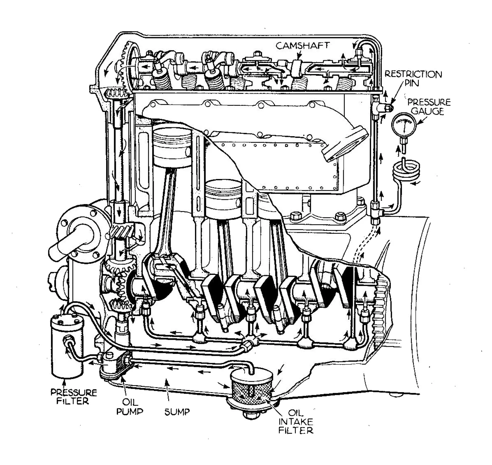
The oil pump forces engine oil at pressure to the spinning bearings, the sliding pistons and the camshaft. That oil cuts friction, lets the engine use bigger fluid bearings, and carries heat away; indeed it is the main route by which heat leaves the pistons, bearings and shafts. If lubrication fails, the engine fails.
Pressurised oil also does other work. It powers hydraulic tappets, one of its first non-lubrication jobs, and increasingly the timing belt tensioner and the variators in variable valve timing systems.
Pressure is not made by the pump alone, but by the resistance the engine puts in its way.
How does an oil pump move oil around the engine?
Oil is drawn out of the sump through a wire-mesh strainer that catches larger debris, then the pump pushes it through the oil filter, sometimes an oil cooler, and into the passages that feed pistons, rings, springs, valve stems and the rest.
The pump is mounted low, either submerged or near the oil level, so it never needs priming. A short pick-up pipe runs to the bottom of the sump. Designs in everyday use include gear, trochoid and vane pumps, whereas plunger types now turn up only in the odd small engine.
How is the pump driven?
Makers choose mechanical pumps for simplicity and reliability, driven by gears linked to the crankshaft. Slowing the pump down helps, so it is common to run it from a camshaft in the block or from the distributor shaft, both of which turn at half engine speed. A near-vertical shaft with helical skew gears reaches down from the camshaft to the pump.
Fiat's Twin Cam engine of 1964 shows how long such a layout can last. It began as an overhead valve engine with a block-mounted camshaft driving the pump. When the twin overhead cam design came, the old arrangement stayed; the camshaft was cut down to a stub shaft, and even when the distributor moved to the cylinder head, the pump drive stayed put and a blanking plate covered the unused distributor hole.
Small engines and scooters may have an internal gear pump sitting directly on the crankshaft. External belts or gears are rare because they are a reliability risk, although tuners adding dry sump pumps sometimes fit separate belts.
Electric pumps are not used as the main pump. A BMW S65, for example, needs about 45 litres a minute at 5.5 bar, which would take a very large motor. Some turbocharged engines carry a small electric "turbo timer" pump that runs after shutdown to send cooling oil to the hot turbocharger bearings, but it supplements the mechanical pump rather than replacing it.
What should engine oil pressure be?
As a rule, an engine builds about 10 psi for every 1000 rpm, peaking around 55 to 65 psi. At the bearing itself, pressure is far higher, reaching hundreds of psi, and it comes from the speed of the journal against the bearing, the bearing's width, the oil's viscosity and temperature, balanced by the clearance through which oil leaks.
The pump's job is only to fill the gap and refresh the oil faster than it leaks away. That is why slow engines can have big journals with modest pumps, and why low pressure means the bearings are leaking faster than the pump delivers.
What does the gauge tell you?
Pressure at the pump outlet is simply the resistance to flow created by clearances and restrictions. A gauge or warning lamp reads the pressure only where its sensor sits. An engine is an open system, because oil returns to the pan through controlled leaks, so the bearing farthest from the pump always has the lowest pressure and worn clearances widen the gap between first and last. An engine can read healthily on the gauge and still have just 5 psi reaching one connecting rod, and that bearing will give out under load.
Cold oil is thicker and pressure is higher at start-up. Once at working temperature, the normal range is typically 30 to 45 psi. A spring-loaded relief valve dumps any excess pressure to the pump's suction side or back to the pan. Too much pressure wastes work and can add air to the oil, and if it spikes it can blow main seals and oil plugs out.
Why does an engine lose oil pressure?
There are four causes: too little oil, a worn pump or broken relief spring, worn main bearings, or a fractured or blocked oil gallery. Connecting-rod big ends are not on the list, since most of their oil arrives by centripetal force.
On an overhead cam engine the cam carrier bearings fail first, because they are fed through a restrictor and low pressure starves the top of the engine. Crankshaft and rod bearings may then seize. Warning signs are the light, a low gauge reading, or clattering and clinking noises.
Wear is the leading culprit. A thousandth of an inch off the main bearings can cost up to 20 percent of oil pressure. Debris is another: the pickup screen has holes about 0.04 square inches (0.26 cm2), big enough to let the thick cold oil through, and a coating just 0.13 mm thick shrinks them to 0.19 cm2, which cuts oil flow by 44 percent. Burning oil from worn piston rings or valve seals can also lower the level in the sump.
Do performance engines need a different oiling system?
Yes. Most road engines do not run much past 5,000 to 6,000 rpm, while performance engines may reach 8000 to 9000 rpm, where oil must circulate fast enough that air does not become trapped in it. Some also use thinner oil, such as 0W-20 rather than the usual 5W-30 or 10W-30, because it needs less power to pump.
A conventional wet sump engine has one pump. A dry sump engine needs at least two: one to pressurise and distribute the oil, and a scavenge pump, with a bigger flow rate, to clear oil that pools at the bottom. The external reservoir lets air escape from the oil, windage falls, and the scavenge vacuum improves ring seal, which is why dry sumps are popular in racing.
What does crankcase ventilation do?
A crankcase ventilation system clears unwanted gases out of the crankcase. Typically it is built from a tube, a one-way valve and some source of vacuum, the inlet manifold being the usual one. The gases are called blow-by: combustion gases that have leaked past the piston rings. Left alone, they condense with oil vapour to form sludge, and the pressure they build can push oil past the crankshaft seals and gaskets.
Two-stroke engines with crankcase compression do not need such a system, because they send crankcase gases to the combustion chamber as a matter of course.
How did early engines vent the crankcase?
For years they did not. Until the early 20th century blow-by escaped through seals and gaskets, and oil dripping from an engine was considered normal, as it had been with steam engines. The gases caused pollution and odours.
The first refinement was the road draught tube: a pipe led from the crankcase, or from the valve cover, to an open end pointing down into the vehicle's slipstream. Moving air across the end created suction. A breather, often in the oil cap, let fresh air in to replace the gases, and many had a scoop in the radiator fan's airflow. Air-cooled Volkswagen and Porsche engines used a reverse screw on the crankshaft pulley to push air in.
The tube worked well at clearing vapours, but it still polluted and could clog with snow or ice, building pressure and causing leaks and gasket failure. Slow delivery vehicles and boats had no useful slipstream, so their breather air was taken from behind the cooling fan, using positive pressure to push gases out.
What is positive crankcase ventilation?
Positive crankcase ventilation, or PCV, sends crankcase gases back into the intake so they burn in the cylinders instead of reaching the atmosphere. The first systems were built in World War II so tank engines could manage deep fording operations, where an ordinary draught tube would have let water in and destroyed the engine.
The emissions purpose came later. Professor Arie Jan Haagen-Smit showed in the early 1950s that car exhaust was a major contributor to the smog crisis in Los Angeles. California set up the Motor Vehicle Pollution Control Board in 1960, a forerunner of the California Air Resources Board, and in 1961 the state required every new car to be sold with a PCV system, the first vehicle emissions control device.
From the 1963 model year most new cars in the United States had it anyway, by voluntary industry action, to avoid building state-specific versions. It soon became standard worldwide for the benefits to emissions, to the engine's internal cleanliness and to oil life.
In 1967 a US federal grand jury looked into claims that the Automobile Manufacturers Association was conspiring to hold smog devices back. After eighteen months it returned a "no-bill", but a consent decree had US manufacturers agree not to work jointly on smog control for ten years.
How does a PCV valve work?
The crankcase breather, usually ducted from the air filter or intake manifold, supplies fresh air, typically through baffles and filters that stop oil mist reaching the air filter. Intake manifold vacuum, applied through the PCV valve, pulls that air through the crankcase and engine, sweeps combustion byproducts away, and carries them into the intake. A properly designed breather keeps the crankcase at a slight negative pressure.
The PCV valve regulates the flow. At idle, manifold vacuum is high and would pull in a large quantity of crankcase gas, making the engine run too lean, so the valve closes. Under load or at higher revs more blow-by is produced, vacuum is lower, and the valve opens. The faster intake flow then means the extra gas does no harm.
The valve also acts as a flame arrester and check valve, shutting when positive pressure appears in the intake, as on a turbocharged engine or in a backfire. Otherwise the pressure could damage crankcase seals and gaskets or even cause an explosion. The outlet, where the valve sits, is placed as far as possible from the breather, such as on opposite valve covers of a V engine.
Forced induction and carbon build-up
Turbocharged and supercharged engines make the valve even more important. Their intake manifold is under positive pressure when loaded, which cannot draw gases from the crankcase and would instead push more in. The valve isolates the two, while cylinder pressures are higher, so more blow-by is produced too.
If the PCV system fails, blow-by can foul the intake with carbon. This rarely troubles port-injected engines because the fuel washes the intake valves on its way in. Direct-injection engines have no such wash, and fuel additives will not clear the deposits. The fixes are spraying cleaner through the intake or media-blasting the valves.
How do crankcase ventilation systems compare?
| System | Where the gases go | Typical use |
|---|---|---|
| Leaking seals | Atmosphere | Early engines |
| Road draught tube | Atmosphere | Cars before PCV |
| PCV valve | Intake manifold | Most modern engines |
| Draught tube to intake | Between air filter and carburettor | Lawn mowers, generators |
| Dry sump scavenge and venturi | Exhaust | Some drag racing cars |
Where this goes next
Vehicle emissions legislation has tightened substantially in the decades since the first PCV rules, and most petrol engines still use PCV systems. Aftermarket oil catch cans and separators are sold to pull oil mist out before it reaches the intake.