Some of the best-known electric cars carry two different kinds of motor. How each works, where the magnets come from, and what the maker is trading off.
A traction motor propels the car. An induction motor induces current in its rotor from the stator field and always runs slightly slower than that field, while a permanent magnet motor uses magnets and is more efficient in applications such as EVs. Makers weigh motor cost, range and battery cost, and some Teslas use both.
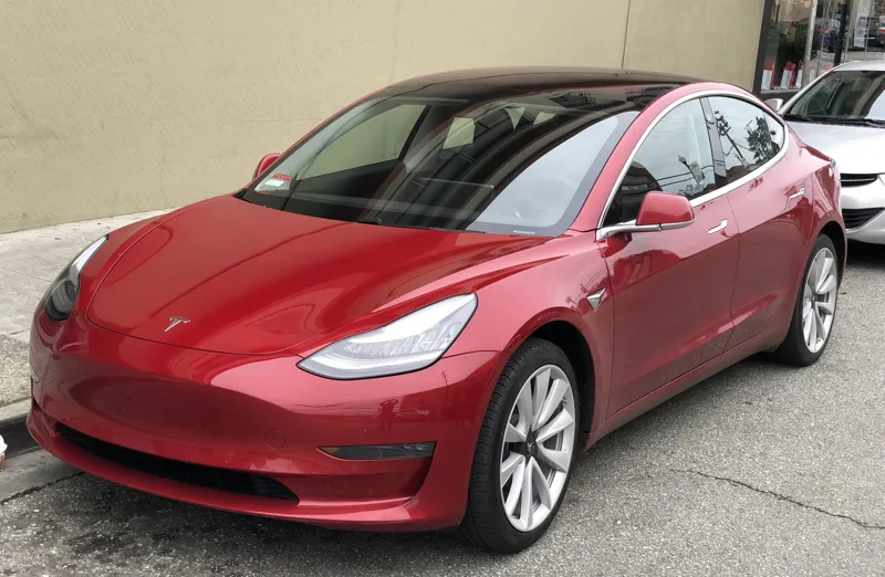
Some of the best-known electric cars carry two different kinds of motor. Recent dual-motor Teslas pair a permanent magnet motor at the back with a traditional induction motor at the front, while the rear drive of the Model 3 and the motors of the Chevrolet Bolt and Volt are permanent magnet designs. The choice is no accident, and the people who make it weigh motor cost, range and battery cost against each other.
What is a traction motor?
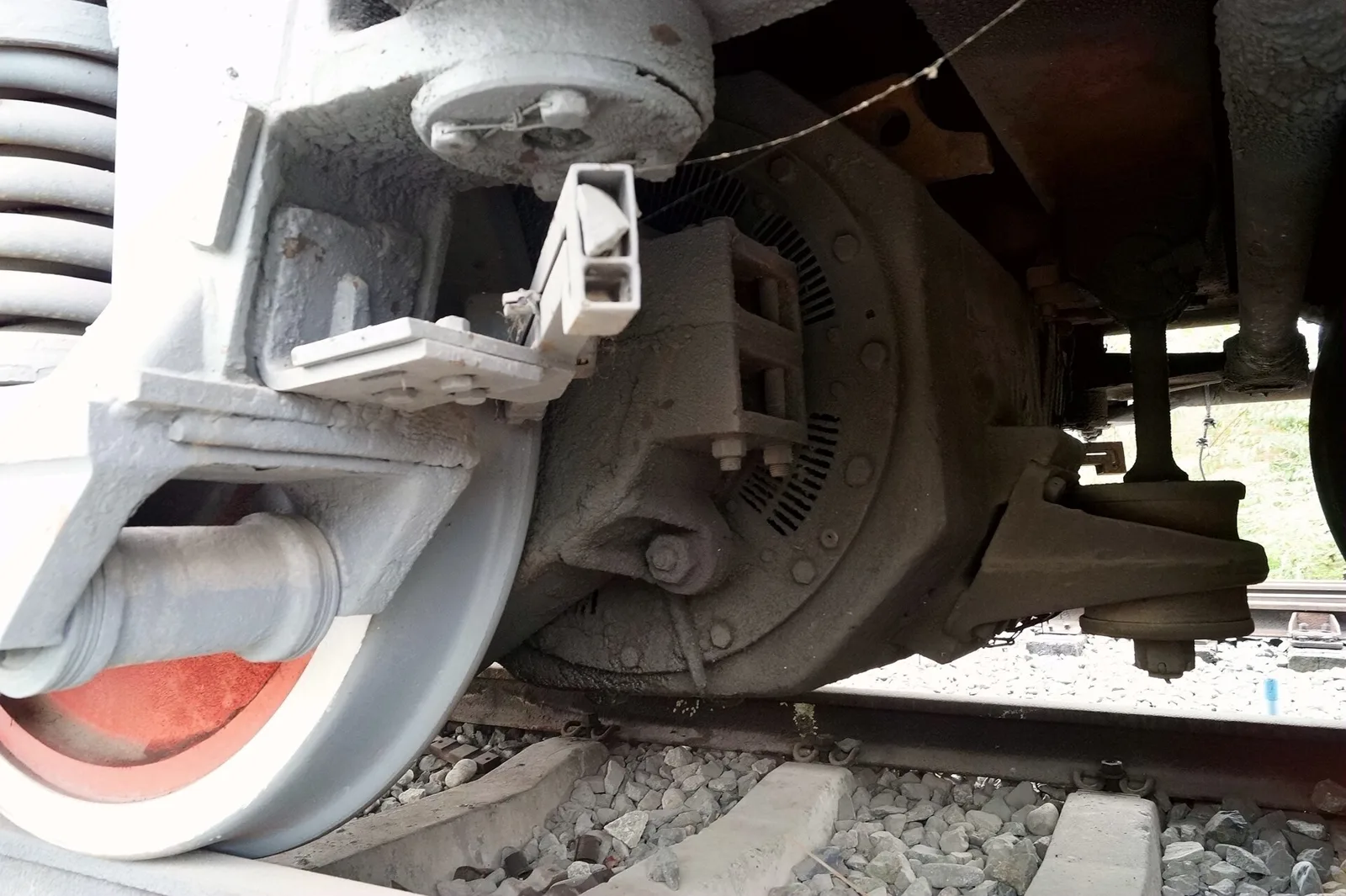
Put simply, a traction motor is the electric machine that drives a vehicle forward. Traction derives from the Latin trahere, meaning to pull; the term was first attached to the traction engines of about 1870. The first experimental electric traction tramway appeared in 1875, and the idea spread quickly through the cities.
Road vehicles took far longer. For most of their history, cars, buses and trucks used petrol or diesel engines with a mechanical or hydraulic transmission. Vehicles with electrical transmission, powered by engines, batteries or fuel cells, began to be developed only in the latter part of the 20th century. Electric machines have another trick: some types can work as a regenerative brake, which slows the vehicle, recovers energy and adds to overall efficiency by charging the battery pack.
From brushed DC to the variable-frequency drive
The oldest traction motors were direct-current machines with series field windings, which deliver high torque at low speed for accelerating the vehicle, and less torque as speed rises. Induction and synchronous AC motors are simple and need little maintenance, but until power semiconductors arrived they were awkward for traction, because an induction motor delivers useful power over only a narrow speed range, dictated by how it is built and by the supply frequency.
Power semiconductors changed that. A variable frequency drive lets the motor run across a wide range of speeds, and it makes rugged induction motors practical, free of the brushes and commutators that wear out in other designs. In railway use, thyristors and the IGBT made simpler, more reliable AC induction motors workable. Cooling is a given at these power levels: forced air, water or a dielectric liquid made for the job almost always does it.
Induction motors follow the field a little behind. Permanent magnets bring their own.
How does an induction motor work?
An induction motor, also called an asynchronous motor, is an AC machine whose rotor current, the thing that makes torque, arrives by electromagnetic induction from the stator winding's magnetic field. No wires need to reach the rotor at all. Three-phase squirrel-cage versions are everywhere in industry, valued as reliable, cheap to run and able to start themselves, and they are increasingly fitted with variable-frequency drives for variable-speed work.
Think of a partner leading a dance who always stays a step ahead. In the stator, AC power creates a magnetic field that rotates in step with the oscillations of the supply. The rotor turns a little slower than that field, so the field sweeps past the rotor conductors and induces current in them, much as a transformer's primary induces current in its secondary. Those currents create magnetic fields of their own in the rotor, and, following Lenz's Law, they push against the change that caused them. The rotor therefore follows the stator field. It accelerates until the induced current and torque balance the load on the shaft.
If the rotor ever caught up with the field, no current would be induced and the pull would vanish. An induction motor therefore always runs slightly slower than synchronous speed. The gap is called slip, and figures for standard Design B torque curve motors range between roughly 0.5% and 5.0%. At full rated load, slip is above 5% for small or special-purpose motors and below 1% for large ones. A four-pole, three-phase motor has a synchronous speed of 1,500 RPM on a 50 Hz supply and 1,800 RPM on 60 Hz.
This is the essential character of the machine: torque comes solely from induction. Nobody separately excites the rotor, as happens in synchronous and DC machines, and it does not magnetise itself, as in permanent magnet motors.
An old idea
The principle is older than the car. Francois Arago worked out in 1824 that rotating magnetic fields exist, and in 1879 Walter Baily demonstrated the effect by turning switches on and off by hand, in effect the first primitive induction motor. The first AC polyphase induction motors without commutators were invented independently by Galileo Ferraris and Nikola Tesla, with a working model demonstrated by Ferraris in 1885 and by Tesla in 1887. Tesla was granted some of his US patents in May 1888, and George Westinghouse licensed them that year. The cage-rotor induction motor came from Mikhail Dolivo-Dobrovolsky in 1889, and by 1896 General Electric and Westinghouse had agreed to license each other's bar-wound rotor design, which became known as the squirrel-cage rotor.
Improvement was steady. Mounting dimensions that held a 7.5-horsepower motor in 1897 would hold one of 100 horsepower by the 1970s.
How does a permanent magnet motor work?
A permanent magnet motor uses permanent magnets to excite the field and has a wound armature. The magnets can stay still or rotate, and can sit inside or outside the armature. There are two main families: permanent magnet DC motors, fed with direct current, and permanent-magnet synchronous motors, fed with alternating current.
Car makers also choose where the magnets go. In a surface permanent magnet motor (SPM) they are on the outside of the rotor, and in an internal permanent magnet motor (IPM) they are inside it. Internal magnets add structural integrity and reduce back EMF. The holes cut into the rotor to take them create areas of high reluctance, so carmakers gain a measure of reluctance-motor benefit on top of the magnets' own.
The back EMF problem
Back electromotive force is a voltage that arises inside a motor because the rotor's magnetic field moves relative to the stator windings. Induction motors suffer from it too, but there the rotor fields fall as speed rises. A permanent magnet motor carries its own constant field, so the voltage induced in the stator climbs in line with speed. That voltage opposes the one supplied to the motor, and so it is a loss to the whole system.
Why do makers choose one over the other?
| Feature | Induction motor | Permanent magnet motor |
|---|---|---|
| Source of the rotor field | Induced by the stator field | Supplied by permanent magnets |
| Rotor speed against the stator field | Slightly slower, by the slip | Same rate in synchronous versions |
| Back EMF as speed rises | Rotor fields decrease | Induced voltage rises linearly with speed |
| Efficiency argument | Perfect flux regulation lets the maker optimise efficiency | Magnets give pre-excitation, an efficiency benefit |
| Examples | Front motor in recent dual-motor Teslas | Chevrolet Bolt and Volt; Model 3 rear drive |
In some high-efficiency uses, electric vehicles among them, permanent magnet motors beat both induction motors and field-wound motors on efficiency. Tesla's chief motor designer has been quoted setting out both sides. By his account, permanent magnet machines gain an efficiency benefit from the pre-excitation that the magnets provide, while induction machines have perfect flux regulation, which lets a maker optimise efficiency. Both suit a variable-speed drive with a single-gear transmission, which is how the drive units of these cars work.
The Model 3 uses a permanent magnet machine, he said, because for the performance and efficiency specification it better solved the cost minimisation question, and suited the range and performance targets best. In his words, the difference is quantitative, and the balance struck between what the motor costs, the range and what the battery costs will settle which technology wins out later.
Where do the magnets come from?
Most industrial uses draw on four materials: neodymium iron boron (NdFeB), strontium carbonate with iron oxide (ceramic, or ferrite), aluminium nickel cobalt (Alnico) and samarium cobalt (SmCo).
| Material | Strength | Curie temperature | Rare earth content and cost |
|---|---|---|---|
| NdFeB | Strongest of all industrial permanent magnets | Approximately 320 C | High cost; neodymium is rare and brings radioactive waste |
| SmCo | Comparable to NdFeB | Above 700 C | More rare earth than NdFeB, so even dearer |
| Alnico | Weaker than NdFeB and SmCo | Nearly 800 C | No rare earth; far cheaper |
| Ceramic | Weaker than SmCo and NdFeB, stronger than Alnico | Around 450 C | No rare earth; lower cost |
NdFeB and its drawbacks
NdFeB sees wide use in electric vehicle motors, alternators, power tools, generators and MRI scanners. It is made mostly by sintering alloyed neodymium, iron and boron, and sintering also leaves it vulnerable to corrosion along the grain boundaries, which has to be countered with copper-nickel or aluminium-based coatings. The metal neodymium is costly and rare, and its production creates radioactive waste, so NdFeB magnets are very expensive financially and environmentally.
SmCo has comparable strength. NdFeB gives a stronger magnetic field, but SmCo has higher coercivity, which means less vulnerability to demagnetisation, and better corrosion resistance and temperature stability. It contains a higher fraction of rare earth metals, though, so it costs even more and is now typically used only in specialty cases, including very high-performance vehicle motors, where its temperature and coercivity advantages count.
Alnico and ceramic magnets contain no rare earths. Alnico is far cheaper and resists corrosion and heat well, but its modest strength leaves it among the magnets that demagnetise most easily. Ceramic magnets are weaker than SmCo and NdFeB, though generally stronger than Alnico, and they are more corrosion resistant and cheaper. They cope less well with hot and cold extremes and lose magnetisation relatively easily.
The supply picture
Producing rare earths generates waste with elevated radioactivity compared with the natural radioactivity of the ores, which the US EPA calls TENORM. In 2010, during a dispute over islands, China, the biggest producer of neodymium, held back shipments to Japan. It also set tight export quotas on several rare earth metals, citing pollution control and the preservation of resources, and lifted them in 2015. Neodymium is relatively abundant, yet global demand for it outstripped production by about 10% in 2017.
What this means for someone buying an electric car
The motor driving the wheels can be of either kind, or both. A Chevrolet Bolt or Volt, or a rear-drive Model 3, has permanent magnet power, while a recent dual-motor Tesla has one of each: magnets at the back, induction at the front. The permanent magnet machines bring a cost in magnets and a back EMF loss that grows with speed, while the induction machine offers perfect flux regulation, and both suit a single-gear drive. Regenerative braking, which the electric machine itself provides, charges the battery pack as the car slows.
Where this goes next
Research into non-rare-earth permanent magnet materials is described as vigorous and ongoing. The aim is a magnet that is low in cost, mechanically robust and high in strength. Candidates attracting interest include ternary alloys of iron, cobalt and molybdenum, nanostructured alloys of cobalt and platinum, and ordered iron-nickel alloys of the type found in meteorites. Which motor technology prevails will, in the words of Tesla's motor designer, hinge on how motor cost, range and battery cost are traded against each other.